Machines with One Winding on the Stator and One winding on the Rotor
The majority of electrical machinery that constitute the backbone of the industry (synchronous generators, induction motors and DC machines) belong to this group. In this kind of doubly-excited machines:
1) Stator and rotor each accommodates one winding.
2) Only heteropolar windings are used.
3) The windings might have any number of phases with equal number of poles.
4) The cores could have smooth or toothed surfaces, but the main attempt is to make the cores surfaces as smooth as possible (by using semi-closed slots), as the change of the self and mutual inductance of the windings due to the teeth of the cores are of the secondary importance; they would only be sources of noise and high frequency losses.
The electromechanical energy conversion is based on the change in the relative position of the windings and the change in their mutual-inductances as the rotor rotates.

Figure 1. An elementary 4-pole synchronous machine
The locations and the directions of currents in the coils of the winding, determine the number of poles. Generally, when they set up a p-pole field, the mutual-inductance L12 undergoes a complete cycle of change when the rotor rotates through two pole-pitches (π radians in Figure 1).
It’s important to notice that as we relate the pole-pitch to the winding span, we always define one pole pitch equal to 180° and not to 360° (Unlike singly-excited machines, where one tooth pitch was equivalent to 360°).:
yp = 2π/p (1)
For example, a four-pole machine has 4 pole-pitch (each of 180°), not two pole-pitch (each of 360°).
Again unlike singly-excited machines, the period of mutual-inductance is determined by the windings pole pitch only and the tooth pitch of the stator or rotor has no effect on the period of the mutual-inductance.
If the rotor rotates at angular speed ωm, the mutual-inductance will alternate with a period equal to:
Te = 2.yp/ωm = 4π / (p.ωm) = 2 / (p . fm) (2)
Where the frequency (and angular frequency) of the mutual-inductance are given by the following formulas:
fe = 1/Te = p.fm / 2
ωe = p/2 . ωm (3)
yp is the pole-pitch of the winding, Te the time period of L12, p the number of poles, fe the frequency of L12 and fm the rotational frequency of the rotor.
The shape of the plot for L12 for a round core with q = 1 is almost triangular and the EMF has an almost square shape. As the number of slots per phase belt q increases, the pattern of change in L12 takes on a stepwise shape close to a sinusoidal waveform.
A practically sinusoidal pattern of change in L12 can be obtained with q = 1 as well, if the air gap at the edges of the rotor teeth are bigger than the air-gap at the teeth axes. In this case the air gap at each tooth axis is chosen two-third to one-half of the air gap at the tooth edge. This type of rotor called Salient-Pole and is usually used in low speed synchronous machines.
As was shown in singly-excited machines, the frequency of the mutual-inductance wave was ZR.fm. Therefore the frequency of self-inductance alternation in a singly-excited machine is 2.ZR/p of frequency of the mutual-inductance of a doubly-excited machine with the same rotor speed.
In synchronous machines, both windings carry currents that their angular frequencies are fixed in advance. The rotor might have a single-phase heteropolar winding (like in a wound-rotor salient-pole machine).
Induction machines are actually singly-excited, but they have two windings each on one element where the stator winding is excited by an AC current and the rotor winding is either short circuited or connected across an impedance, and the current in this winding is built up by electromagnetic induction. The rotor current frequency is different from the stator current frequency.
Induction machines could have wound rotors or squirrel cage type which constitute a large percentage of induction motors. The squirrel cage rotor consists of metal bars (Aluminum or Copper) pushed through the rotor slots and shorted at both ends by rings.
Not similar to synchronous and induction machines that have rotating magnetic fields in the air gap, both windings in DC machines set up fixed and stationary fields that stay perpendicular to each other at all speeds. Perpendicularity of these two fields is maintained by the action of a mechanical device called Commutator that accomplishes the switching of individual armature coils in a well established manner. The continuous perpendicularity of these two fields is the main reason why power density of DC machines is usually higher that those of synchronous and induction machines.
Machines with Two Windings on the Stator and A Toothed Rotor (Inductor Machines)
These machines are usually used in special purpose applications and have the following unique features:
1) Both windings are on only one the stationary element, so no need to slip rings or brushes.
2) Both windings could be heteropolar with the same or different number of poles.
3) Both windings could be homopolar.
4) A heteropolar and a homopolar winding could be combined.
5) Depending on the design, the stator might be toothed or smooth, but the rotor must always be toothed.
As compared to a conventional synchronous machine, an inductor machine has usually a substantially larger size and weight. The flux density in the toothed surface of the stator (or rotor) in an inductor machine varies only in magnitude, whereas in a conventional synchronous machine it is rotating and varies in both magnitude and direction. Given the same geometrical dimensions and maximum tooth flux density, the peak value of the fundamental flux in an inductor machine would be smaller than its value in a conventional synchronous machine. Therefore, the application of inductor machines is justified only in those cases where the desired frequency is difficult to obtain by a conventional multipole or a claw-pole synchronous machine.
Among their unique features, they are the only kind of mechanoelectrical devices that without any field on their rotors (and without any auxiliary devices), are able to work as a generator. This makes them as a unique solution in very special applications.
The electromechanical energy conversion is due to the variations in the mutual-inductance L12 of the two windings as the toothed rotor rotates relative to them. variations of self-inductances are of secondary importance, although this change might be even higher than the mutual-inductance. Like singly-excited machines, one cycle of the change in the mutual-inductance is completed as the rotor rotates through one tooth pitch.
If the rotor is rotating at an angular speed ωm, the time period and angular frequency of the mutual inductance can be found by the same relations that were obtained here for singly-excited machines:
Te = αR / ωm = 2π / (ZR . ωm) = 1 / (ZR . fm)
fe = 1 / Te = ZR . fm
ωe = ZR . ωm (4)
Practical Designs
There are three different kinds that depend on the type of windings on the stator:
1. Both windings are heteropolar.
2. One winding is heteropolar and the other homopolar.
3. Both windings are homopolar.
In all the above three cases the rotor is toothed.
- The mutual-inductance between the two heteropolar windings on the stator is made to vary owing to the rotation of a toothed rotor core. The windings usually different number of poles and the higher-pole winding plays the role of the carrier signal of the lower-pole winding. Remembering the synchronous reluctance machine that discussed in singly-excited machines, where we made the rotor with an equal number of teeth as the stator winding poles, here we should have the rotor teeth equal to P1 + P2 or P1 – P2. In this arrangement, as both winding are on stator, its saliency is of minor significance. As the permeance wave is constant (due to smoothness of the stator core), it’s quite difficult to find all acceptable combinations. Here is a brief guideline (assuming P1 > P2):
i) If P1/P2 = 2K (an even number)
L12 has a zero average and all odd number of teeth work, but a rotor with number of teeth equal to ZR = P1/2±P2/2 has the largest variations in the mutual-inductance (and hence biggest EMF).
 Figure 2. Two heteropolar 4 & 2 pole windings, ZR = (4+2)/2 = 3
ii) If P1/P2 = 2k+1 (an odd number)
L12 has a non-zero average and all even number of rotor teeth work, but a rotor with number of teeth equal to ZR = P1±P2 has the largest variations in the mutual-inductance (and hence biggest EMF).
 Figure 3. Two heteropolar 6 & 2 pole windings, ZR = 6 – 2 = 4
iii) If P1/P2 is a fractional number
Then L12 has a zero average and only two combinations ZR = (P±P2)/2 and ZR = (P1±2P2)/2 have acceptable inductance waveforms.
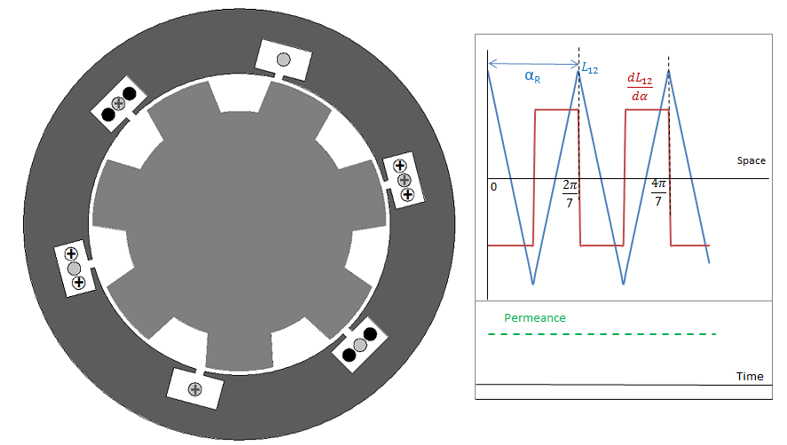
Figure 4. Two heteropolar 6 & 4 pole windings, ZR = (6+2×4)/2 = 7
Number of rotor teeth ZR is uniquely fixed by the specified frequency and the rotor speed. Usually it is very large and to satisfy the above relations, winding 1 must have a low number of poles and winding 2 a large number of poles.
- The mutual-inductance between a heteropolar and a homopolar winding is made to vary by the rotation of a toothed rotor core relative to a smooth or toothed stator core.

Figure 5. One homopolar and one 6-pole heteropolar windings, ZR = 9+6/2 = 12
