Some fundamental windings and core designs capable of producing a spatially periodic magnetic field were discussed Here.
We are now interested in finding those configurations that while their self (or mutual) inductances depend on the rotor position, they change periodically as the rotor changes position.
Considering a drum machine, we will study that in how many different ways and how an electric machine must be configured so that the self or mutual inductances of its windings to be functions of the angular position of the rotor and change periodically as the rotor rotates. Meanwhile we will find out some rules for maximizing the developed inductances.
Smooth and Toothed Cores
The currents flowing in the windings, produce magnetic field (poles N and S) in the core carrying the windings; where the core’s teeth only affect the shape of the field in the air gap. Therefore, as long as a core carries at least one winding, with either a smooth or toothed surface, it would experience changes in the self-inductance of its winding (or mutual inductance between its windings). When a core accommodates winding (or windings), a smooth surface (with semi-closed slots) always performs better (due to saturation, closed slots behave like semi-closed slots in practice).
If the core (a rotor for example) doesn’t accommodate a winding, it can not have its own magnetic field and its magnetic field (N and S poles) must be created by the stator. To the stator magnetic field (disregarding how many poles it has), all positions of a smooth rotor would be the same. Therefore the rotor must be toothed where the number of teeth, play an important role in the characteristic and performance of the machine even if the stator has physically closed slots, since as was mentioned, saturation effects open the closed slots.
Rotation of a toothed rotor, will change the reluctance of the paths of flux lines linking the stator windings. In some cases when the insertion of the windings requires an open slot design for the stator core, we need to pay attention that with toothed cores, in most cases, the permeance of the air gap is changed in space or/and time, which leads to undesirable effects if not addressed properly.
Basic Machines Types
In the following elementary models, only the motoring mode of operation will be considered, disregarding if they are directly reversible or not. In addition, as electric machines have usually two magnetic elements (stator and rotor), we consider maximum two windings.
With two elements of stator and rotor and maximum two windings, the following three combinations could exist:
- A singly-excited machine with one winding on the stator and no winding on the rotor. The stator could have smooth or toothed surface but the rotor must have a toothed surface. The periodic self-inductance has a non-zero average value.
- Two doubly-excited machines where we could have any of the following combinations:
i) A machine with one winding on the stator and one winding on the rotor. Both stator and rotor could have smooth or toothed surfaces. The periodic mutual inductance has a zero average value.
ii) A machine with two windings on the stator. The stator could have smooth or toothed surface but the rotor must have a toothed surface. The periodic mutual inductance could have a zero or non-zero average value depending on the design.
The magnetic field in the air gap may be either heteropolar or homopolar according to the winding used. Homopolar windings could only be single-phase and operate on AC or DC, but heteropolar windings could have any number of phases and operate on AC or DC depending on the configuration and interfaces.
Wavelength Equation In Rotational Motion
In linear motion, the relation between a wavelength λ, its speed v and time period T is:
λ = v . T (1)
The relation between an angle θ and the corresponding arc is: S = R.θ (where R, θ and S are radius, angle of rotation and the subtended arc respectively). If arc S is equal to wavelength λ (λ = R.θ), then in rotational motion, the wave equation (1) transforms to:
R.θ = v . T ⇒ θ = v/R . T
Since v = R.ω, we will have the familiar equation:
θ = ω . T (2)
Equation (2) is the basic equation used in all of the following topics.
Heteropolar Integer-Slot Windings (Reluctance Machines)
In a machine with one winding on the stator and a toothed rotor core, electromechanical energy conversion is the result of variations in the self-inductance of the winding as the toothed rotor rotates and changes the reluctance of the magnetic circuit (thereby self-inductance L11 changes) where the name reluctance machine came from.
The winding in Figure 1 is a concentrated single-phase winding, but it could have any number of phases.

Figure 1. A single-phase 4-pole reluctance machine (ZS=8 and ZR=8)
In a singly-excited machine, both stator and rotor could be toothed. But the self-inductance of the stator winding is maximum when the stator has a smooth surface (semi-closed slots). In stators with semi-closed slots, not only the developed EMF is higher but also the EMF shape is closer to a sinusoidal one.
L11 undergoes a complete cycle of change when the rotor rotates through one tooth pitch αR.
It is important to note that the pole pitch and tooth pitch of the stator have no effect on the period of the self-inductance (and the speed of motor).
If the rotor rotates at angular speed ωm then the time period and frequency of the self-inductance is calculated by the following equations:
Ti = αR / ωm = 2π/ (ZR . ωm)
fi = 1/Ti = ZR . ωm / 2π = ZR . fm
ωi = ZR . ωm (3)
Ti is the time period of L11, ZR the number of rotor teeth, fi the frequency of the self-inductance and fm the rotation frequency of the rotor.
As we will see later in doubly-excited machines (like synchronous machines) the relation between the frequency of the mutual-inductance and the rotor is: fi = (p/2) . fm where we conclude that in reluctance machines, the self-inductance frequency is 2ZR/p of mutual-inductance frequency in an equivalent synchronous machine of the same number of poles and rotor speed.
To have a regular steady-state torque (without cogging and radial torques), the permeance wave must be periodic so have a constant shape and amplitude in all poles. To meet this requirement, the rotor and stator teeth must occupy the same relative positions at every pole in every position of the rotor. It can easily be shown that to fulfill this condition, the number of stator and rotor teeth must follow the following rule:
ZS/p – ZR/p = ±k
ZS – ZR = ±k.p (4)
Where p stands for the number of stator winding poles and k is an integer number k=1, 2, 3, …. The ± sign is for taking into consideration that the stator teeth could be more or less than rotor teeth. In using Equation (4), we must exclude, all those combinations where in them ZS/ZR or ZR/ZS is an integer number, where they lead to a large variation in air-gap permeance; for example, combination ZS=12 and ZR=4.
Therefore, to have a satisfactory operation, not only the the rotor and stator pole-pitches must be integer numbers, but also they must differ by a non-zero integer number. Then at every pole, there would be an equal area of opposite tooth-tooth surfaces. For example, if a stator made of ZS = 16 teeth has a 4-pole winding , then the rotor could have 4, 8 and 12, 20, 24 etc teeth. If we use a distributed winding the change in in self-inductance and the induced voltage will be close to a sinusoidal shape:
 Figure 2. A single-phase 4-pole reluctance machine (ZS=16 and ZR=12)
Equation (4) not only assures a smooth permeance wave in the air gap, but also maximum variations in the self-inductance and consequently maximum developed EMF. But the ingenuity of the design engineer plays the most important role in choosing the best configuration to guarantee the highest performance.
Assuming the same number of poles and frequency, the highest rotor speed can be attained when the rotor has the minimum number of teeth or when ZR = number of stator winding poles. Such a rotor is called Salient Pole and the machine is called Synchronous Reluctance Machine (SRM).
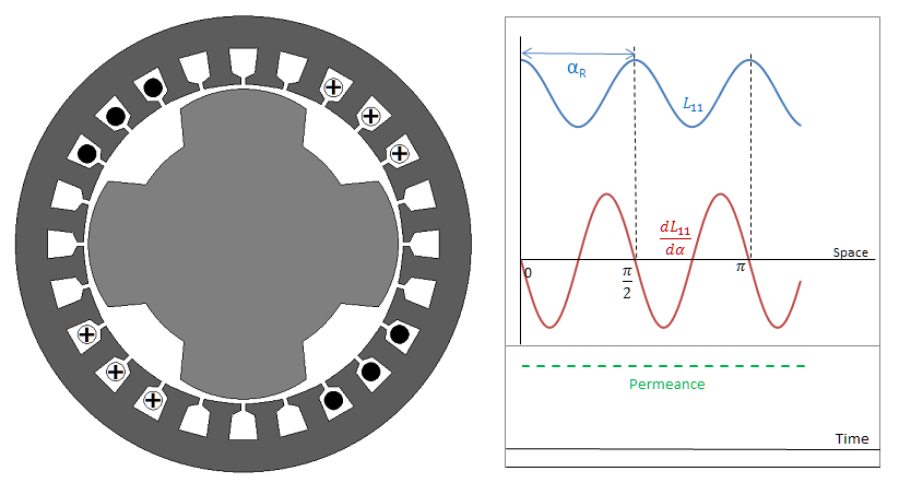
Figure 3. A 4-pole reluctance machine with salient pole rotor (ZS=24, ZR=4)
The time period, frequency of the self-inductance and rotor speed are still given by Equations (3).
Heteropolar Fractional-Slot Windings (Reluctance Machines)
Despite small phase group slots (q), fractional-slot windings develop the best shapes for L11 and the induced voltages (almost sinusoidal), but as (ZS/p) is a fractional number, in no condition they can produce a constant permeance wave in the air gap. Figure 4 shows a single-phase winding of an 18/4 slots/pole synchronous reluctance machine with sinusoidal L11 and EMF. With open slots, the permeance wave has about 20% fluctuation along the air gap and the motor will experience a light mode 2 radial vibration.
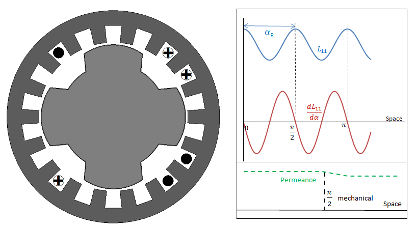
Figure 4. A 4-pole SRM with single-phase, single-layer fractional-slot winding (ZS=18, ZR=4)
With semi closed slots, the fluctuation of permeance wave could be reduced to under 10%.
Homopolar Windings
To create a field with the same number of poles as the number of teeth we can either use a heteropolar winding with the same (or half) the number of coils or just use a homopolar winding (or coil) that builds up a field with a number of poles twice as many as the number of slots (or teeth) and it’s done by a simple coil that embraces the rotor (the internal core).
As explained here, for each pole on the outer surface of the rotor core, there is a pole with opposite polarity on the inner surface of the stator core. It means that in singly-excited machines, we cannot choose different number of slots (or teeth) for the stator and the rotor when using homopolar winding, so ZR = ZS.
When the number of teeth on the cores is the same, the permeance wave has the highest fluctuations in time. The time period, frequency and rotor speed of the self-inductance are still found by equations (3).
