Before a discussion of drum windings that constitute the majority of the winding types used in the industry nowadays, we need to get familiar with varieties of windings from different points of views.
In this discussion, only distributed three-phase windings (q > 1) will be considered. Windings with q=1 are called concentrated windings and since all space harmonics have a winding factor of 1, are rarely used in practice.
In addition, in the diagrams, the connections between groups are considered series where could be parallel without affecting our discussions.
Types of Classifications
As discussed here, a heteropolar winding creates alternative magnetic poles on the side of the core facing the air gap. The distance between the first and last slots that accommodate a coil’s sides is called coil throw. For example, if one side of a coil is in slot number 5 and the other side in slot number 15, then the coil throw is 15-5 = 10 slots.
The pole-pitch is defined as:
![]()
And its unit is slot. For example in a 24/4 slots/pole winding, the pole-pitch is 24/4 = 6 slots.
In a winding, disregarding the throw of the coils and whether the coils are similar or have different throws, the average coil span is a unique number and is considered as the winding span. When it is equal to the pole pitch, the winding is called a full-pitched winding.
Hetero-polar winding can be categorized in different ways:
1) Whether they are closed or open
2) Their topology (ring or drum)
3) If the coils are pre-formed or inserted strand by strand (form or mush)
4) Number of layers in each slot
5) The type of end connections (spiral, lap or wave)
1. Open and Closed
All heteropolar windings belong to one or the other of the two types, one with an open geometry or a closed one.
An open winding is the one in which, starting with any conductor and tracing progressively through the winding, a ” dead-end ” is finally reached.
Whereas in a closed winding, the starting point will finally be reached after having passed through all, or some sub-multiple of the coils.
Nowadays, DC machines are always constructed with armature winding of the closed type.
In AC machines with odd number of phases, depending on the phase connection, the winding could be closed or open. In three-phase windings connected in Y, the winding is of the open type, while in ∆ connected ones, the winding is of the closed type.
A ∆ (or Y) winding interface with the three-phase supply is at three points separated by 120º, which is definitely different from the way a DC machine commutator serves as an interface between the armature winding and the single-phase DC power supply.
AC machines with even number of phases, always use the open type winding.
2. Ring and Drum
The ring winding (Gramme ring) is one in which, the coils are wound in and out around the core in helical fashion.
In this winding, the coils are usually connected successively to each other so as to form a continuous circuit. The main disadvantage of ring winding is that there are conducting wires outside of the core (if we use it on stator side) which do not cut the flux lines and which do not, therefore, contribute to the EMF buildup and electromagnetic energy conversion, Figure 1. 
Figure 1. Ring and drum coils
The drum winding (Figure 1) was developed (by Hefner-Alteneck and Siemens in 1873) to reduce the amount of dead wire in a ring winding. Each coil is wound on the inner surface of the stator (and the outer surface of the rotor), with both coils sides inserted in the slots on the same side of the core along the shaft.
The drum armature may be thought of as evolved from the ring type by moving the outer connections of the coils to the inner surface, at the same time stretching the coil circumferentially until the spread of the coil is approximately a pole pitch.
Ring windings are not used anymore, but in a short stack with a very large stator bore and low number of poles (especially with a relatively narrow stator yoke), using ring winding could be justifiable.
Ring windings are especially useful for educational purposes in DC machines and in future posts, I will use them often. But in AC windings discussion we don’t talk about them any more.
3. Formed and Mush (Random)
In designing an AC machine, we cannot constantly increase the power rating just by increasing the geometric dimensions. To keep the amount of flux density (while increasing the dimensions), analytic calculation shows that the coils turns have to be reduced, where with more increase in dimensions, they become even smaller than one (without a physical meaning). To keep the number of coils turns in an appropriate level (for more easily winding too), we have two options:
1) Reducing the working frequency
2) Increasing the working voltage level
The frequency is dependent on the network and cannot be generally changed (except in inverter driven machines). So the only option would be increasing the voltage level where the coils need to have stronger (and thicker) electrical insulation and a definite clearance (depending on voltage level) from each other. That’s when we use form (or preformed) coils. The coils are made of enameled rectangular copper wires (wrapped by layers of insulation), with a diamond shape and are usually built by special equipment. The stators must have open slot, so the coils can be inserted.
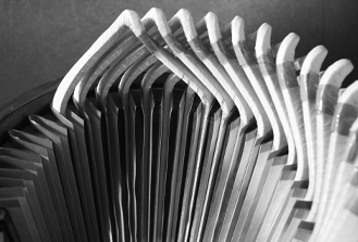
Figure 2. Form winding
Mush winding is made of enameled round copper wires and the coils are inserted strand by strand (manually or automatically) in semi-closed stator slots. As the magnet wires are randomly inserted in the slots, so often called random winding.

Figure 3. Mush (Random) winding
4. Number of Layers
All full-pitched windings can be of a single-layer type. As the harmonics cannot be fully controlled in them, single-layer windings are not used for large electric machines:
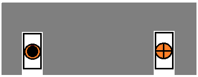 Figure 4. Single-Layer Winding
To reduce space harmonics, in addition to using a distributed winding, we can use a double-layer winding where we have the option of choosing a winding span different from the pole pitch (usually smaller). In double-layer windings, with some slots and poles combinations, we can even remove a specific annoying space harmonic.
In integer-slot winding, with a winding span different from the pole pitch, we cannot use a single-layer type at all, but in fractional-slot winding (where the winding span is always different from the pole pitch), in some cases we can use the single-layer type.
A single-layer winding can always be replaced by the double-layer type, but the opposite is not true.
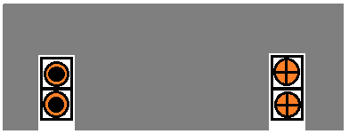
Figure 5. Double-Layer Winding
5. Types of End Connections
The end connections of a distributed winding may be arranged in several ways, all electrically identical, as shown in Figures 6-8. All these diagrams are of half-coiled (will be explained soon) type. The coils throw, the order they are connected together and grouped, give rise to three different configuration:

Figure 6. Spiral

Figure 7. Lap

Figure 8. Wave
As was mentioned in Basic Rules, as long as you keep the positions and current flowing directions, you can make any other pattern, but probably won’t be of any practical use.
Practical Winding Patterns
Differed mainly by the type of the end-connection, the following configurations constitute the majority of the windings used nowadays.
1. Concentric
Generally only mush windings are of concentric type (form windings could be of concentric type too, but are not recommended at all). It could be half-coiled (unbifurcated) or whole-coiled (bifurcated), where both can be done with single or double-layer configurations.
All concentric windings use the spiral end connection type. Due to the shape of end winding that resembles concentric circles, it is usually called concentric.
i) Single-layer
As was already mentioned, in a single-layer winding the average coil-span is equal to the pole-pitch. It could be made of half-coiled groups or whole-coiled ones which could have major manufacturing differences.
In half-coiled winding (or group per pole-pair), each group of coils, uses the whole phase-group slots (so has as many coils as the number of phase groups slots) and creates two poles.
This configuration is not used in two-pole windings.
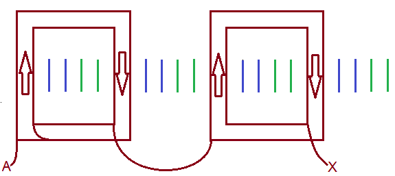
Figure 9. Half-coiled concentric 24/4 slots/pole
In whole-coiled winding (or group per pole), the phase group splits to two usually equal sub-groups where each sub-group accommodates half of the coils and creates one pole.
 Figure 10. Whole-coiled concentric 24/4 slots/pole
The end-winding dimension in half-coiled type is axially longer but radially narrower. The order of groups insertion could be planned somehow so the end winding comprises two concentric circles.
The end-winding dimension in whole-coil type is axially shorter but radially thicker and it comprises three concentric circles.
ii) Double-layer
Double-layer winding is made of two interleaved single-layer windings; before interleaving, depending on the winding span, one would be shifted one or few slots.
double-layer concentric winding can be used when we want to simulate a lap (or wave) winding with short-pitched coils and instead of manual insertion of coils, use automatic equipment to achieve faster manufacturing time.
Figures 11 and 12 show concentric windings equivalent of a lap winding with coil spans = 5/6:
 Figure 11. Two single-layer whole-coiled concentric (shifted 1 slot)
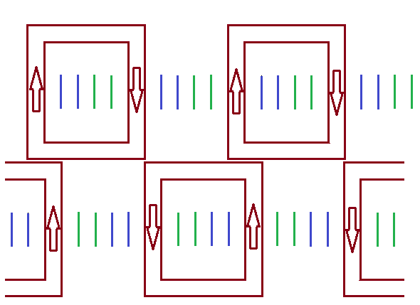 Figure 12. Two single-layer half-coiled concentric (shifted 1 slot)
All double-layer windings are of whole-coiled type, so the connections between the groups are done similar to Figure 10:

Figure 13. Double-layer concentric 24/4 slots/pole (coil span = 5/6)
2. Lap
Figure 14 shows a single-layer lap ( the successive coils lap back over each
other) winding which is not used in AC machines, but with some change it is used in universal motors armature, where the geometric symmetry is of importance:
 Figure 14. Single-layer lap 24/4 slots/pole
The same way that we interleaved two single-layer concentric type to a double-layer one, we can use two single-layer lap winding and build a double-layer lap winding:
 Figure 15. Two single-layer half-coiled lap (shifted 1 slot)
Figure 16 shows the resulting double-layer winding where all coils are similar and not only geometrically but also magnetically symmetrical (if one side of a coil lays at a slot bottom, the other side will lay at another slot’s top). In other words, the slot and end winding leakage reactances of all phases are the same. Both mush and form coils can use lap winding. To control the space harmonics, the coils span is usually shorter than the pole-pitch which both reduces the harmonics and helps with lower coil resistance and less copper loss.
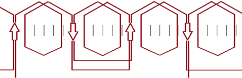
Figure 16. Double-layer lap 24/4 slots/pole (coil span = 5/6)
3. Wave
In wave winding, the coils progress continuously in a wave fashion around the periphery of the armature. The procedure from a single-layer to double-layer is like a lap winding, so only the resulting double-layer is shown:
Figure 17. Double-layer wave 24/4 slots/pole (coil span = 5/6)
In DC machines, lap and wave winding have different features and depending on the application, one might be preferred to the other.
In AC machines, they are almost the same. They only differ in the total length of the wire required to make the coils and coils connections. With a large number of coils turns and phase belt slots, the effect of coils ends is insignificant and the total wire would practically be the same. With a small number of phase group slots (2 or 3), a large number of poles and a small number of coil turns (especially when it is one), wave winding is more attractive. Then the saving in copper might be 5-10%.

I liked this. I use parts of in my lectures. My name is RObert Nilssen professor at NTNU and Zhejiang university in China.