There are two simple but important rules in the windings theory:
- When the positions and directions of the currents for each phase are known, then for analysis purposes, it doesn’t matter how they are interconnected or where the currents start and end. In other words, as long as the interconnections among the current paths don’t make any change in the already determined positions and directions of currents, the topology of the end winding could be neglected.
Only the part of windings embedded inside the slots, are cut by the flux lines and develop EMF; the interconnection of the current paths (which lay out out of the slots with their flux lines closed in the air) are just important from manufacturing point of view; where it should be practical and economical. - In all symmetrical three-phase windings, either an integer-slot or fractional-slot, the sequence of phases is always as AZB for pole N and XCY for pole S.
- AZB and XCY each makes a pole. A and X indicate the two ends of phase A (current flows up in A and flows down in X); B and Y the two ends of Phase B (current flows up in B and flows down in Y) and C and Z the two ends of phase C (current flows up in C and flows down in Z). The current direction must be interpreted as a way of signifying the start or end of a coil group (it flows up at the start side and flows down at the end side). The real direction of current in phase C (of a three-phase system) is opposite, but you don’t need to consider it for our discussion.
The following picture shows the currents layout for an elementary winding of 6/2 slots/pole:
Figure 2. An elementary winding with 6/2 slots/pole
The slot pitch is equal to 2×180⁰/6=60⁰. The first pole N is made by AZB and the second pole S is made by XCY. The phases are shifted by 120⁰ in space. For a winding more than 2-pole, this cycle repeats until covers all the poles.
As a typical example; here is how the currents positions and directions of a 3-phase, 24/4 slots/pole winding are calculated.
An important parameter is the number of slots per phase per pole or q and is defined as:
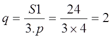
Another technical term for q is the number of slots per phase group (or belt). In the above equation, each phase group (or belt) occupies 2 slots. This winding that has an integer q, is called Integer-Slot winding.
Considering the second rule mentioned above, the following configuration results:
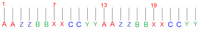 Figure 3. Layout of the winding with 24/4 slots/pole
As is seen the first and third poles follow sequence AZB and the second and forth poles XCY.
In A, B and C the currents of the corresponding phases flow up and from X, Y and Z the currents flow down.
By choosing the type of winding (either single or double layer) considering the currents directions, the whole winding layout is specified.
Another important parameter is the slot pitch which is defined as:
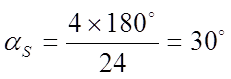
Assuming the angle of the first slot at zero, the following layout displays the angles of all slots in the example winding:

Figure 4. Slot angles of the winding 24/4 slots/pole
After subtracting 180⁰ from all those slot angles that are equal or bigger than 180⁰ (as many times as required until the angle is less than 180⁰) the following layout results:

Figure 5. The above Winding with reduced slot angles to less than 180⁰
As is seen, the angles of every consequent 6 slots are the same as each other. 6 is the pole pitch and equals to the number of slots a pole occupy: 24/4 = 6.
If the first and third 6-slot groups build north poles, the second and forth 6-slot groups build south poles.
The above rules could be used as the key for arranging a typical three-phase winding in any brand of a 2D/3D FE analysis software.
