Background
Fractional-slot windings were invented for some purpose that was totally different and limited from what they were later used for.
Assume that the armature of a three-phase salient-pole synchronous generator is designed with nine slots per pole (like in a 108/12 slots/pole stator with q = 3 slots) and that the rotor pole arc embraces 60% of the pole pitch. As the rotor poles rotate relative to the armature, the number of slots under each pole face will be alternately five and six, which leads to a pulsation in the permeance of the main magnetic circuit and thereby set up a high frequency harmonic in the induced voltage. Problem may arise when this harmonic has such amplitude as to cause interference with telephone circuits in the vicinity of the lines supplied by the generator. To solve the problem, the generator must be redesigned with 99/12 slots/pole instead, where the pole face sees the same number of stator slots in all times. The new stator design would require a fractional-slot winding with q = 11/4 = 2.75.
This kind of winding is the most complicated and interesting type and has some unique uses like in PAM, BLAC/DC motors and when the same lamination wanted to be used for variety of poles. Especially in high-pole windings where the phase groups cannot have more than two slots, fractional-slot winding is a universal choice.
Nowadays, electronically commutated motors (ECM or so called BLAC/DC) that utilize fractional-slot windings, constitute the most interesting and demanded ones where q is not only a fractional number, but also it is smaller than one, which leads to a winding with coils span = 1.
Due to difference in poles widths in fractional-slot windings, they produce even harmonics in addition to odd harmonics. Except few, a large class of fractional-slot windings produce a number of harmonics that are not integer multiples of the main harmonic. These harmonics called sub-harmonics, are usually stronger than the slot and space harmonics and could lead to an uncontrollable level of noise and vibration.
Analysis
As an example of a fractional-slot winding, consider a stator of 18/4 slots/pole where the number of slots per each phase group is equal to:
 (1)
(1)
Or 3 coils per a pole pair.
In integer-slot windings, q (the number of slots per phase group) is an integer number (the denominator is one) and there are an integer number of slots per each phase group. Therefore all phase groups have the same number of slots.
In the above example, because 3 slots cannot be shared between 2 poles equally, the only approach would be assigning 2 slots for one pole and 1 slot for the next. We define a ‘unit’ as the number of slots that accommodates 2 poles (the denominator). Later we see that in fractional-slot windings ‘units’ play the role of poles as in integer-slot windings.
The slot pitch is 4×180⁰/18 = 40⁰. Here is the arrangement of slots angles for this winding:

Figure 1. Slot angles in a winding with 18/4 slots/pole
By subtracting 180⁰ from all those slot angles that are bigger than 180⁰ (as many times as required until the angle is less than 180⁰) the following layout results. As is seen, slots 10 to 18 have the same angles as slots 1 to 9 which means our units are made of 9 slots. From q=3/2 we conclude that each unit consists of 2 poles (and 3×3=9 slots).
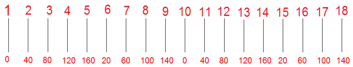 Figure 2. Slot angles after subtraction of multiple 180⁰
The problem now changes to finding a winding for a 9/2 slots/pole configuration. The favorite 18/4 slots/pole is made of 2 similar units of 9/2 slots/pole:
 Figure 3. Slot angles in one unit
In integer-slot windings, the angles of slots were: 0, αs, 2αs, 3αs, 4αs, etc (αs is the slot pitch). But the above diagram shows something different; the slot angle increases sequentially up to slot 5 and then drops to 20º (half the slot pitch); and then continues with the same order.
The above diagram indicates that the winding poles don’t span 180° anymore but only 90°, which is the result of reduction of the slot pitch αs from 40° to 20° (half).
Rearranging the slots according to their angles knowing that each phase consists of 3 coils, we have:
 Figure 4. Dividing the unit to three equal groups
To distinguish three phases, each set of three consecutive slots have different colors. With Red for A, Green for B and Blue for C, notice that the order of AZB has been followed. In other words, the first 3 slots (1, 6 and 2) belong to phase A, the next 3 slots (7, 3, 8) to phase Z (end of phase C) and slots 4, 9 and 5 belong to phase B.
From Figure 4, we can find the rule for the layout of a fractional-slot winding.
Supposing that the consecutive slots of the same phase are separated by equal distances; then we have the following relation (x is the distance (per number of slots) from the former slot in the same phase. n is denominator of the q and K is an integer number):
 (2)
(2)
Remember what we did to get the layout in Figure 4; we subtracted as many 180º from the slot angles until the angles were between 0 and 180º. After this subtraction, the distance between any two consecutive slots were αs/2.
After solving for x we have:

 (3)
(3)
It is clear that 180n/αs is equal to the number of slots in a unit. From the other side, we know that number of slots in a unit is equal to 3m and we finally have:
 (4)
(4)
Where it means: to find the distance of phase group slots in a fractional-slot winding we have to find the smallest integer number x by trying K=0, 1, 2, 3, etc in the above formula. From the above equation it is seen that if n=3, then we cannot find any integer number for K to make x integer. It means the necessary condition for a three-phase fractional-slot winding to be balanced is that n≠3k (k = 1, 2, 3, …).
In this example the smallest integer x is equal to:
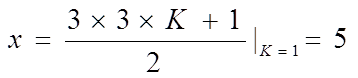 (5)
(5)
As it’s shown below, the sequential slots (of the same phase) from their angle point of view, are spaced by 5 slots:
 Figure 5. Rearranging the coils according to equation (5)
The arrangement is the same as the original one in Figure 3 except for the colors that separates phases from each other. Therefore second slot of phase R is 1+5 = 6 and the third slot of phase R is 6+5 = 11 which in the diagram is equal to 11 – 9 = 2.
So far, we were just concerned about obtaining a diagram that specifies the location of phases’ slots (and the directions of the corresponding flowing currents). The above procedure can be used for building every kind of three-phase double-layer fractional-slot windings directly. A small family of double-layer fractional-slot windings can be reduced to single-layer ones which require some manipulation. I leave it to the diligent readers to find the procedure.

Hello i am kavin, its my first time to commenting anywhere, when i read this piece of writing i thought i could also make comment due to this brilliant piece of writing.